Assembly
Tools Needed
- Needle Nose Pliers
- Screw-driver set
- Allen key set
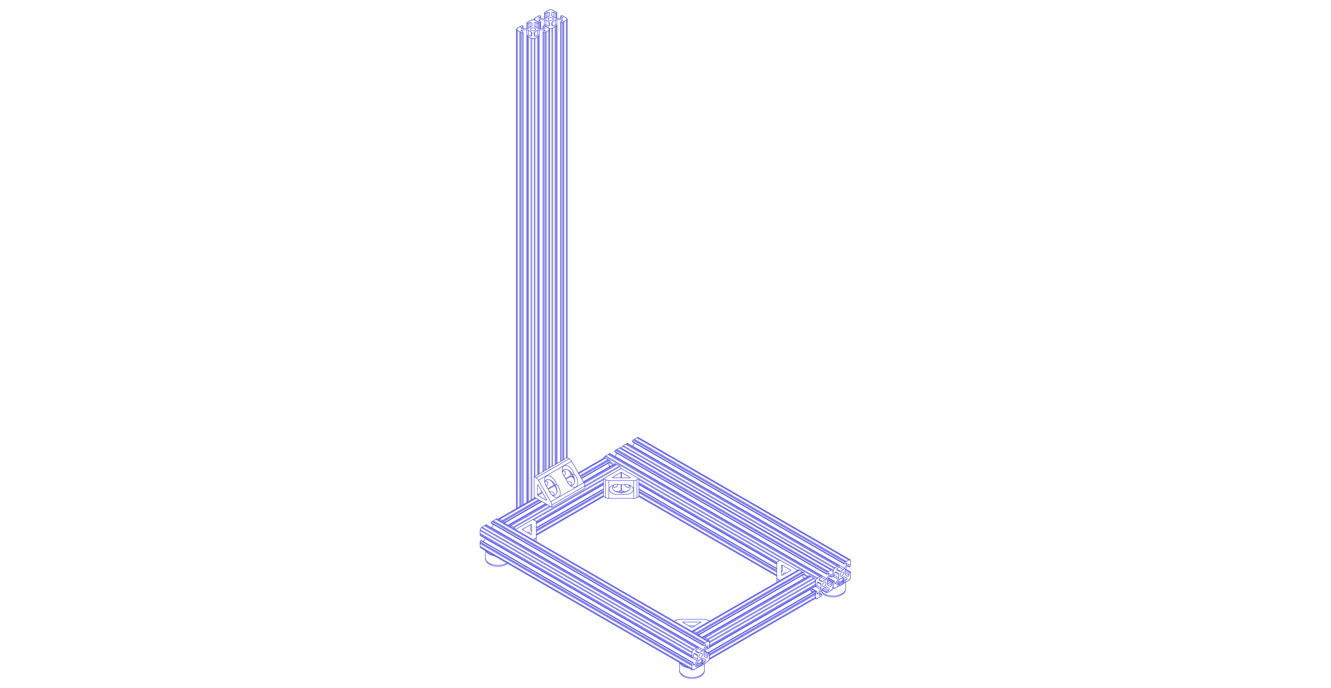
I. Frame
Base Frame
- Place down one
12" single railand one12" double railboth on their 1" x 12" side. - In between the two rail, place two
6" single railon either end so the four rails form a 9" x 12" rectangle. - Prepare Screws for Tank Stands
- Loosely screw together 4 sets of
cap screwsandT-nuts. - Slide 2 assembled screws onto the
12" single railsand 2 onto the12" double rails. - Make sure the screws face the inside of the frame-rectangle.
- Loosely screw together 4 sets of
- Attach the frames together using 8
cap screws, 8T-nuts, and 4single brackets. - Attach a
bumperbelow each corner (4 total).
Vertical Frame
- Orient the rectangular framing such that the
12" double railis on the right. - Behind the farther
6" single rail, center one24" double railoriented vertically with a 2" side flush with the frame. - Attach the
24" double railto the base frame using 4cap screws, 4T-nuts, and adouble bracket.
II. Syringe Pump
Syringe Holders
- Attach a
cap screwandT-nutto each screw hole of the 3-D printed syringe pump mechanisms.
When attaching the screws, leave room for the pieces to slide onto the framing.
TheT-nutshould be on the flat side of the print. - Slide the
syringe hub holderonto the24" double railoriented like an “L”. - Tighten the screws when the holder is 5.5" above the rectangular frame.
- Slide the
flange holderonto the24" double railoriented like an upside-down “L”. - Tighten the screws when the
flange holderand thesyringe hub holdercan fit yoursyringe.
Ours is approximately 5.25" apart at their farthest edges.
Syringe Displacer
- Place the
steel hex nutinto thesyringe displacer'shexagonal slot and slide it into place.
The threaded part of thenutshould align with the circular cutout on thedisplacer. - Place the
linear bearinginto thesyringe displacer'scircular hole.
You want the bearing to be flush with the syringe cutout. - Spin the
threaded rodinto thesteel hex nutuntil thesyringe displaceris around the middle of thethreaded rod. - Slide one
motion shaftinto thelinear bearing. - Place the
motion shaftand thethreaded rodinto their corresponding hole in theflange holder.
Themotion shaftis closer to the frame, thethreaded rodis farther.
Syringe Motor
- Attach the 8mm end of the
rigid couplerto the top of thethreaded rodusing twoM4 set screws. - Attach the
syringe motorto thesyringe motor mountusing 4M3 screws. The wire should face left or right. - Slide the
syringe motor mountonto the framing so the motor shaft fits into therigid coupler.
Also, themotion shaftfits intosyringe motor mount'scylindrical extrusion. - Secure the motor to the coupler with 2
M4 set screws. - Tighten the mount’s
cap screws.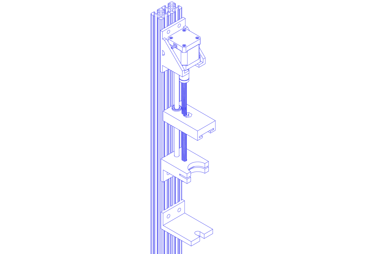
III. Baths
Assemble Rod Posts
- Place a
nylon hex nutinto the 3D printedaxel'shexagonal slot. - Slide the
axelinto apostand secure with anylon screw. - Snap two
plastic ball bearingsonto theaxlewith the bearings facing out. Eventually, you want the metal bearings to be facing away from the baths. - Repeat steps 1-3 two more times (3 assembled rod posts total).
Attach Passive Roller Posts
Note: orient all the rod posts so that the bearings’ metal parts face out.
- Orient the frame so that the
24" double railis furthest from you. - On the
12" single rail, place one assembledpostwith its bottom edge 2.25" from the bottom of the frame. - Repeat step 2 with
12" double rail'sleft rail. - Attach both
poststo theframewith 4cap screwsand 4T-nuts.
Attach Motorized Roller Posts
- On the
12" single rail, place anotherpostwith its top edge 3.25" from the top of the frame. - Attach the
roller motorto the 3D printedroller motor mountwith fourM3 screws. The wire should face down. - On the
12" double rail’s right half, place theroller motor mountwith its bottom edge 2.25" from the bottom of the frame. The wire faces away from the frame. - Attach the
roller motor mountandpostto the frame with 4cap screwsand 4T-nuts.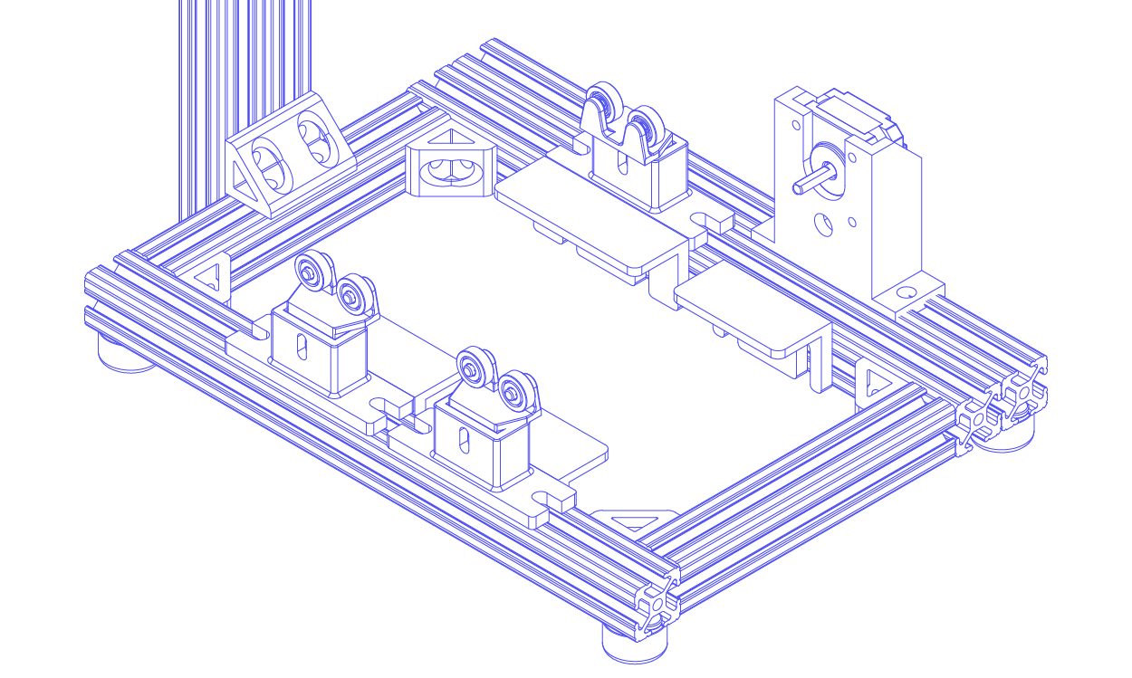
Attach Tanks
Note: tank stands are attached on the inside of the frame in an upside down “L” shape
- Beneath a passive rod
post, attach awide tank standusing the two pre-attached screws farther from you. - Repeat step 1 for the other passive rod
post. - Beneath the motorized rod
post, attach anarrow tank standusing the remaining pre-attached screws. - Repeat step 3 for the
roller motor mount. - Place the
coagulation bathon thewide tank stand. - Place the
wash bathon thenarrow tank stand.
IV. Collectors
Assemble Passive Roller
- Slide one
rolleronto onemotion shaft. - Slide a
shaft sleeveon either side of theroller. - Place the
rolleronto the passive rod posts, aligning theshaft sleeveswith theplastic ball bearings.
Assemble Motorized Roller
- Slide the second
rolleronto the othermotion shaft. - Slide a
shaft sleeveon only one end of themotion shaft. - On the other end, attach the 8mm side of the
flexible couplerusing twoM4 set screws. - Attach the 5mm end of the
flexible couplerto theroller motorusing twoM4 set screws. - Align the
shaft sleevewith theplastic ball bearingson the other side.
Secure Rollers
- Position the
rollersin the middle of the tanks. - Slide an
M2 nutinto each slot of each roller. - Secure the
rollersto themotion shaftswithM2 screws(4 nuts and 4 screws total).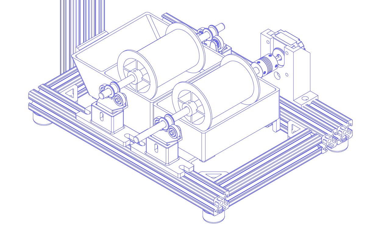
V. Controller Box
Attach PCB
- Place the prepared PCB inside the 3D printed
controller box, ensure the connectors match the outlets on the box. - Secure the PCB with 4
M3 screws.
Assemble Controller Panel
- Remove the threaded ring from the
pushbutton, insert thepushbuttoninto the dedicated slot on the controller top panel. - Secure the
pushbuttonwith the threaded ring. - Remove the nut from the
potentiometer, insert thepotentiometerinto the dedicated slot on the controller top panel. - Secure the
potentiometerwith the nut using a plier. - Place the
displayinto the dedicated slot on the controller top panel. - Secure the
displaywith 4M2 screwswith nuts.
Connecting Wires
- Plug the
pushbutton cableinto theBTN_DIRconnector on the PCB. - Plug the
potentiometer cableinto thePOT1connector on the PCB. - Plug the
display cableinto theOLEDconnector on the PCB. - Plug the
pedal cableinto thePEDALconnector on the PCB
Close the Controller Panel
- Use 4
M2 screwsto attach thecontroller panelonto the controller box
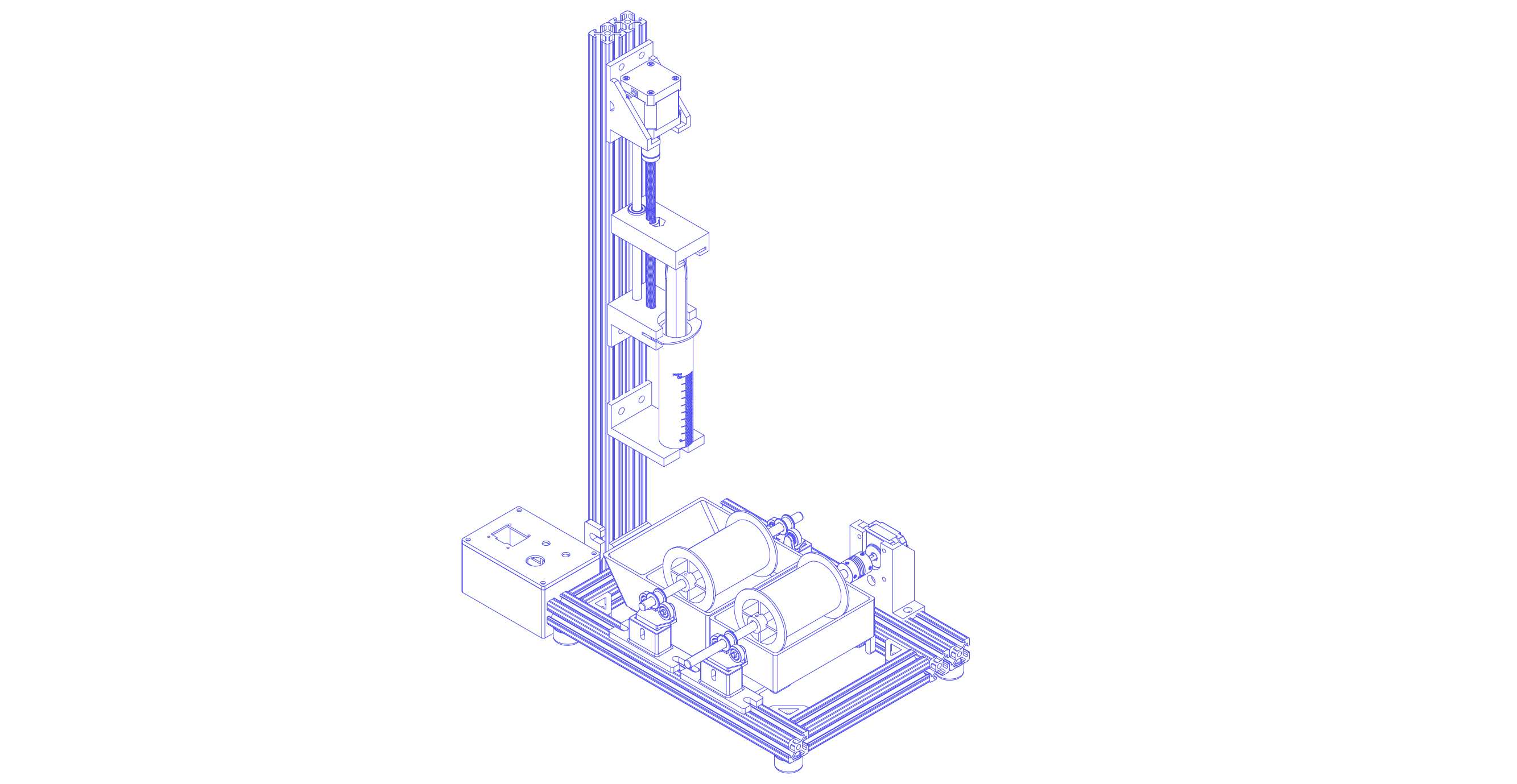
VI. Assemble Full System
Last updated on