PCB Preparation
Order PCB
We ordered the PCB from JLC PCB with the following configurations:
- Base Material: FR-4
- Layers: 2
- PCB Thickness: 1.6mm
- Copper Weight: 1oz
Note: There is no need to order a stencil as there is only one surface mount soldering component.
Tools Needed
- Soldering iron
- Solder wire
- Tweezers
- Breadboard
PCB Soldering
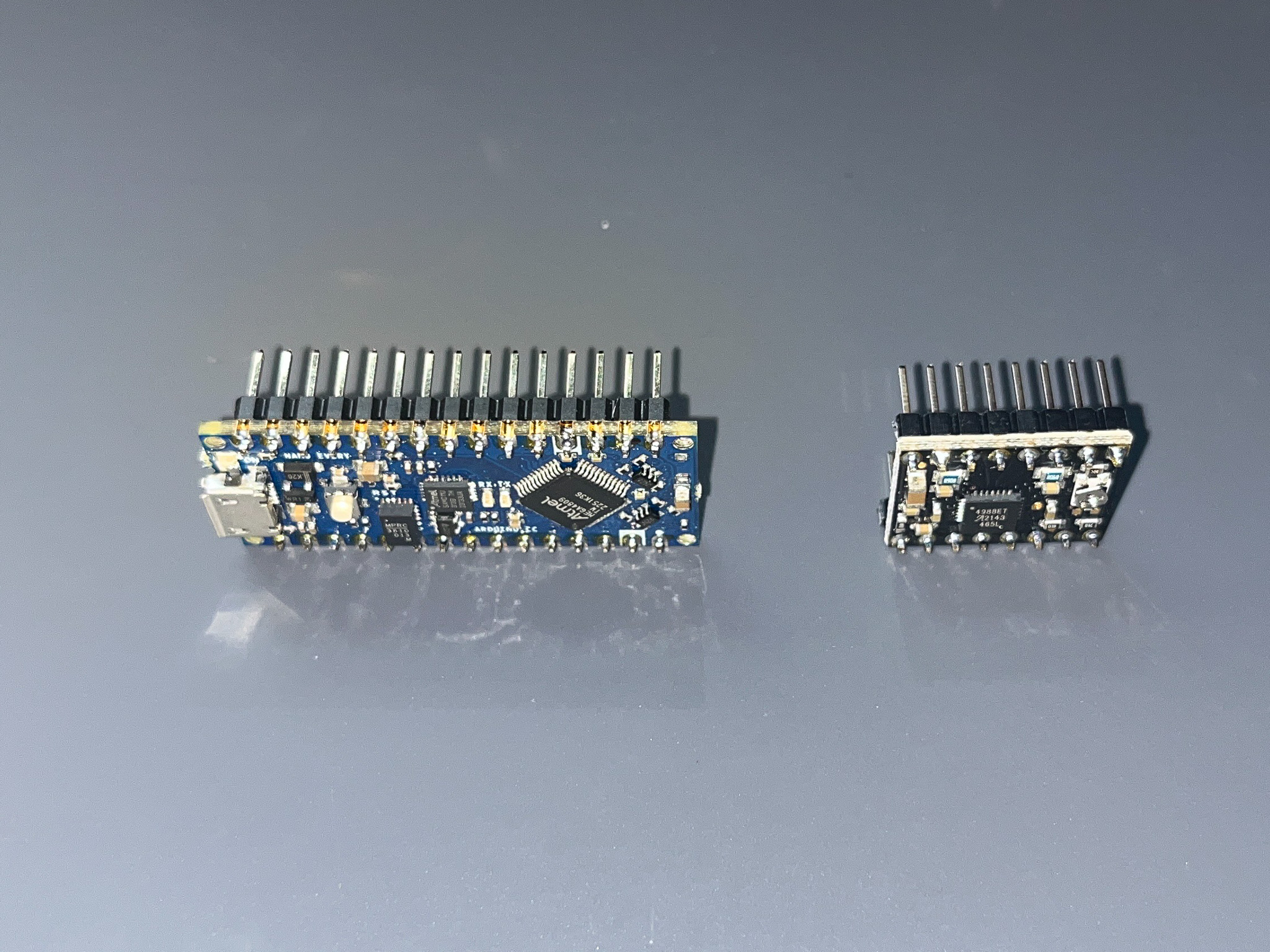
Prepare Breakout Boards
- Solder header pins to breakout boards
Arduino Nano Everyand 2A4988 Motor Driveron a breadboard to ensure headers are correctly algined.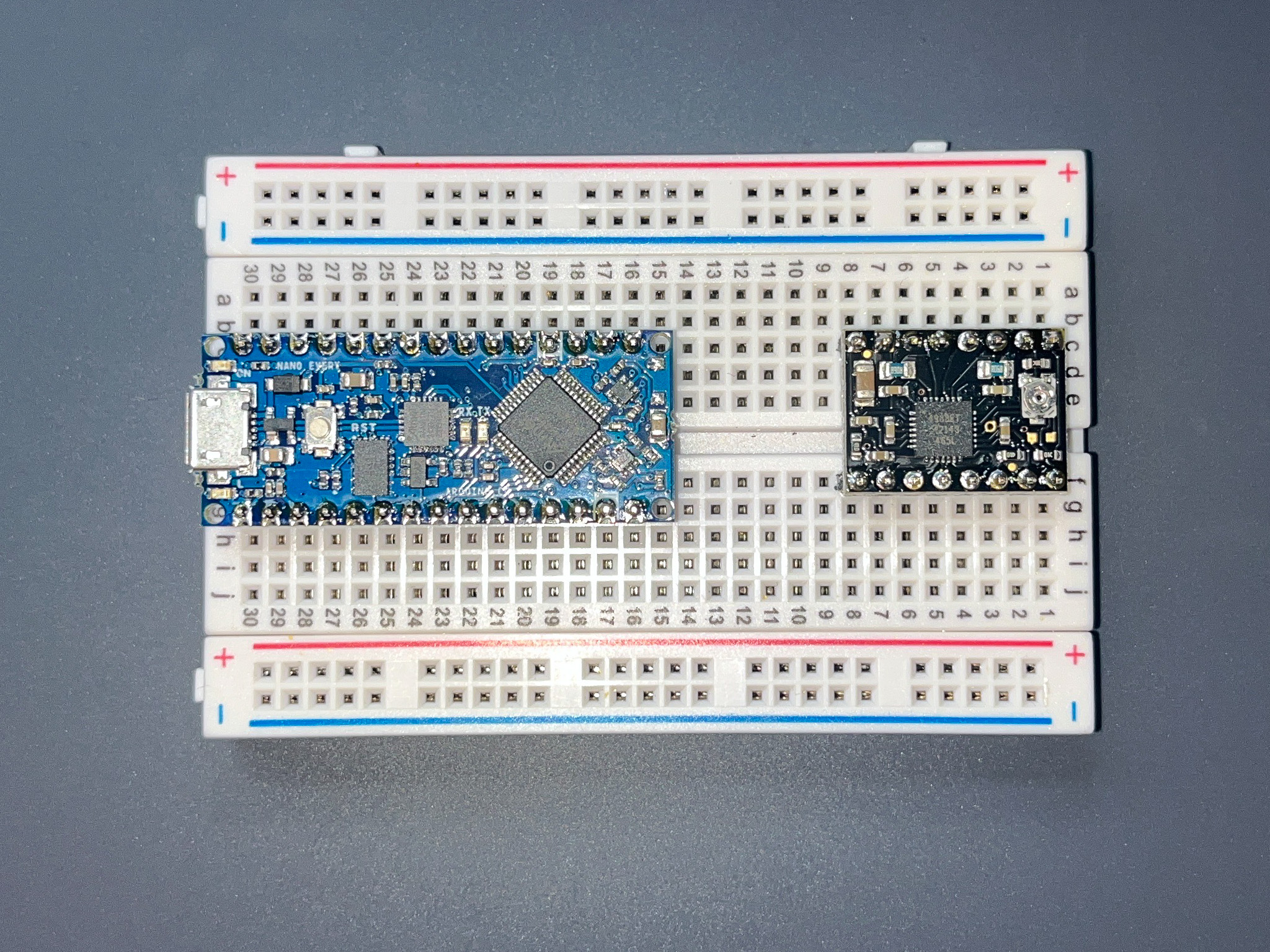
Solder Breakout Board Connectors
- Solder surface-mount
OLED connectoronto theOLEDposition on the PCB.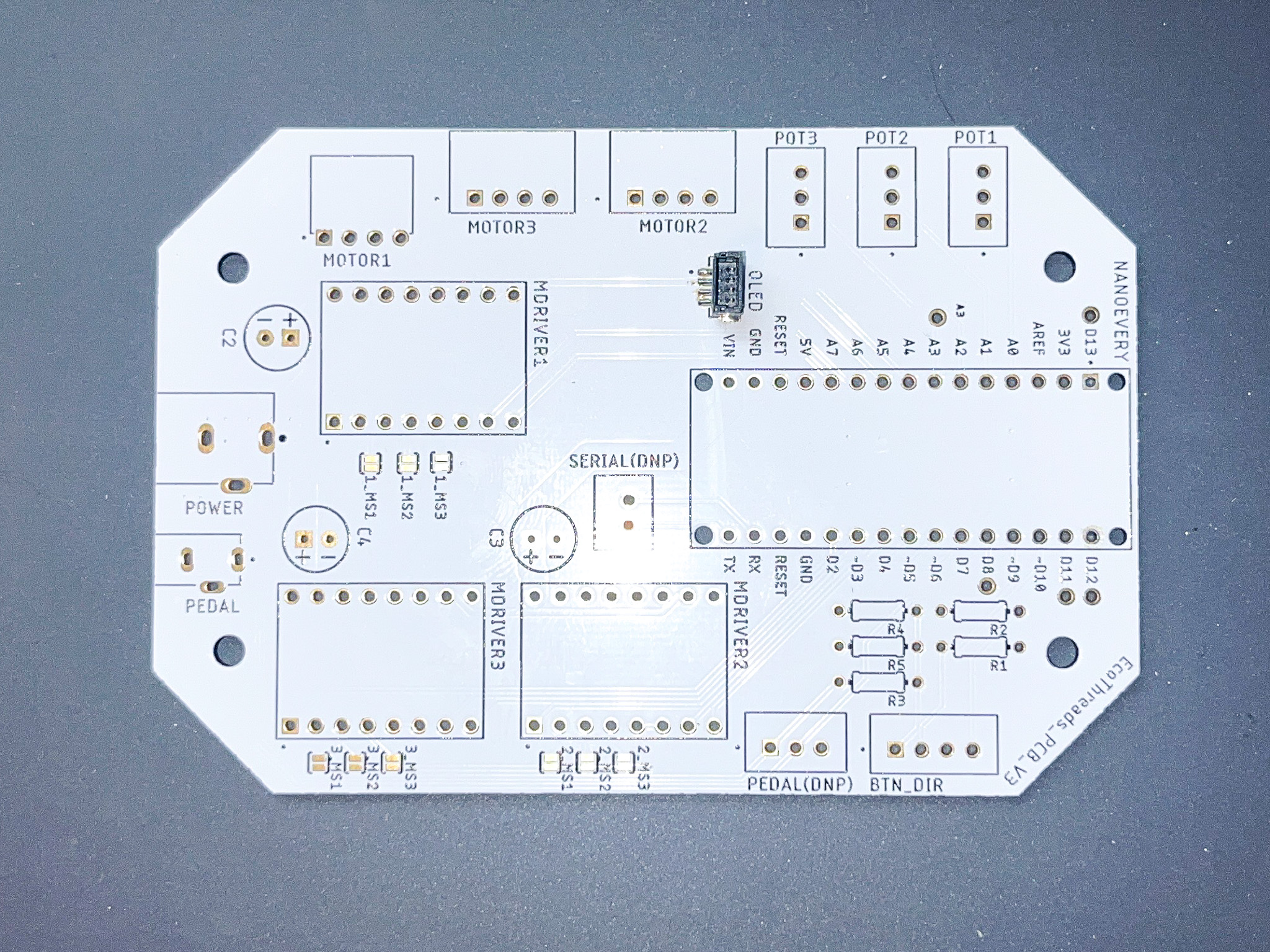
- Solder through-hole connectors for
NANOEVERY,MDRIVER1,MDRIVER2,MDRIVER3according to the Bill of Materials.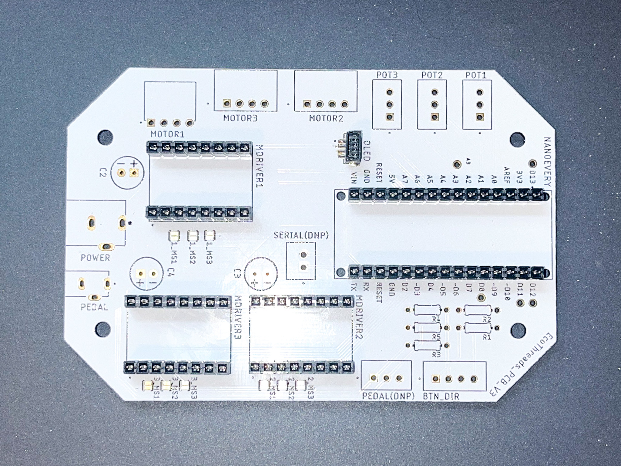
Solder Passives
- Solder resistors to 300 ohm resistor to
R2, and 10k ohm resistor toR1, R3-R5.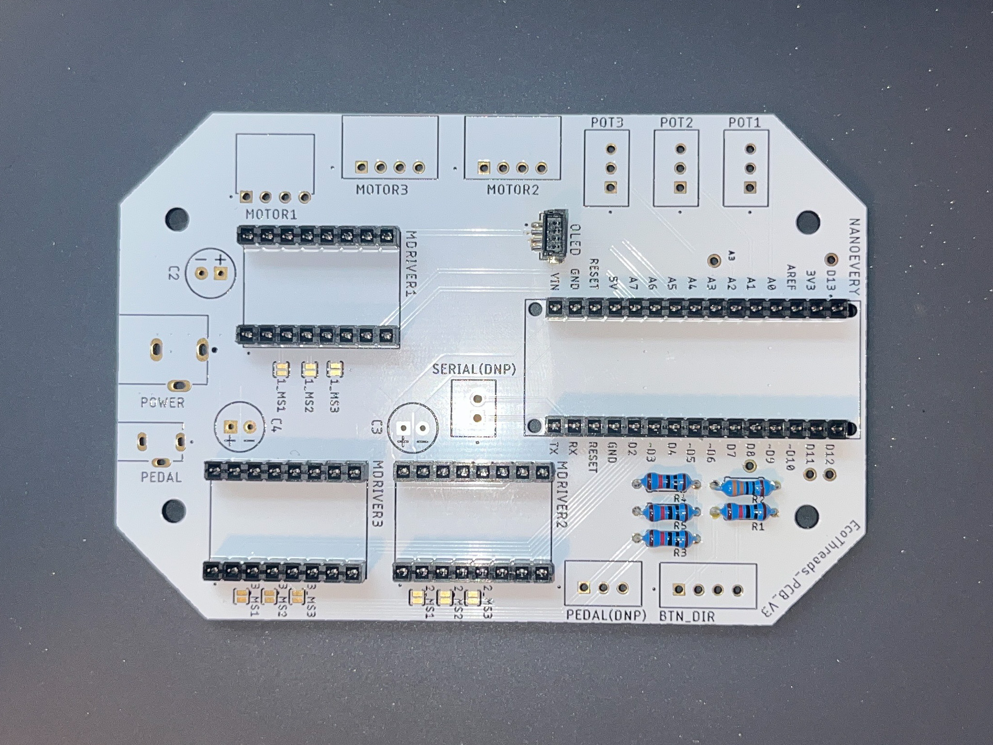
- Solder 100uF capacitors to
C1, C2, C3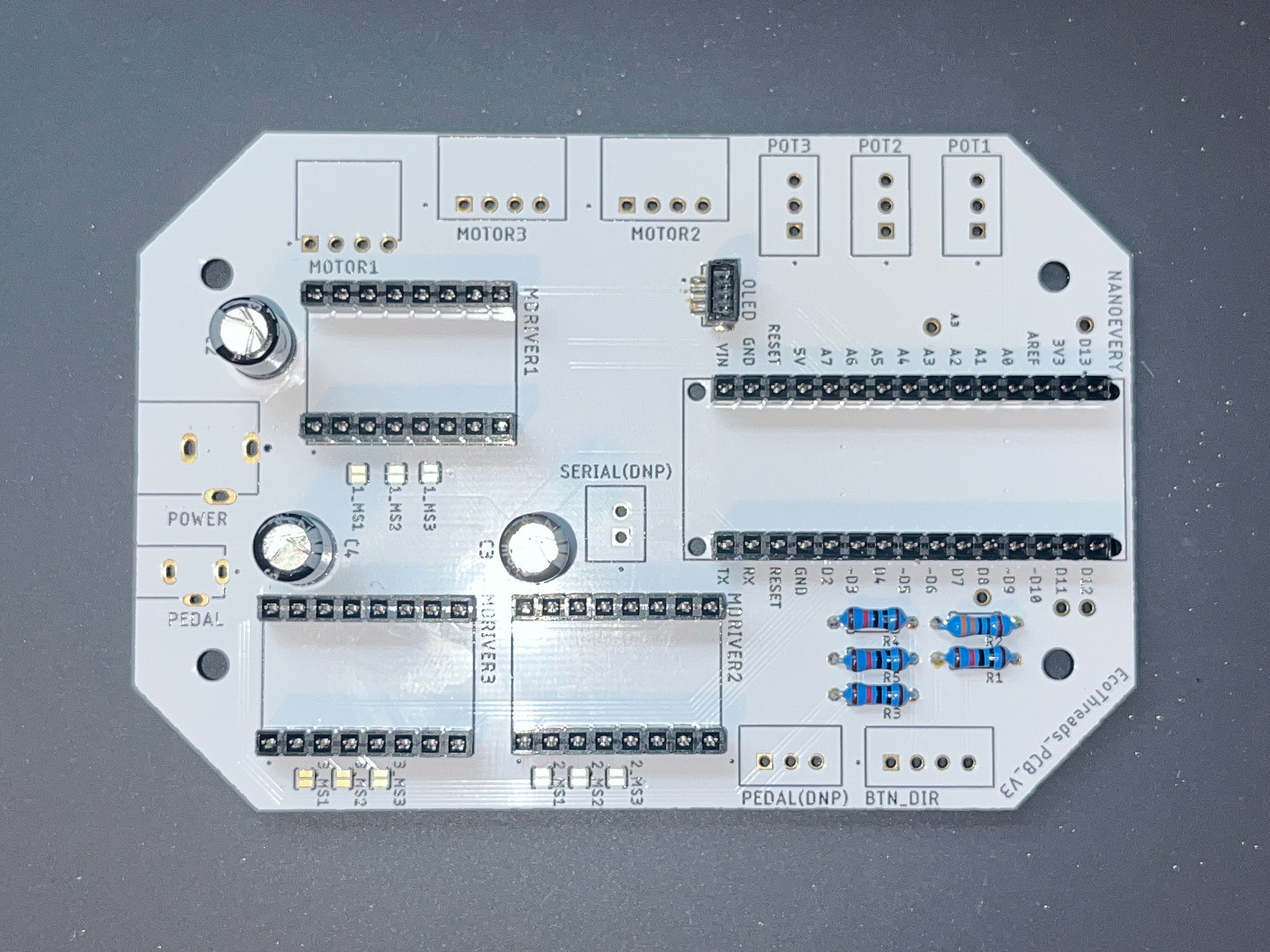
Solder Wire Connectors on PCB
- Solder through-hole connectors for
MOTOR1,MOTOR2,MOTOR3,POT1,POT2,POT3,BTN_DIRaccording to the Bill of Materials.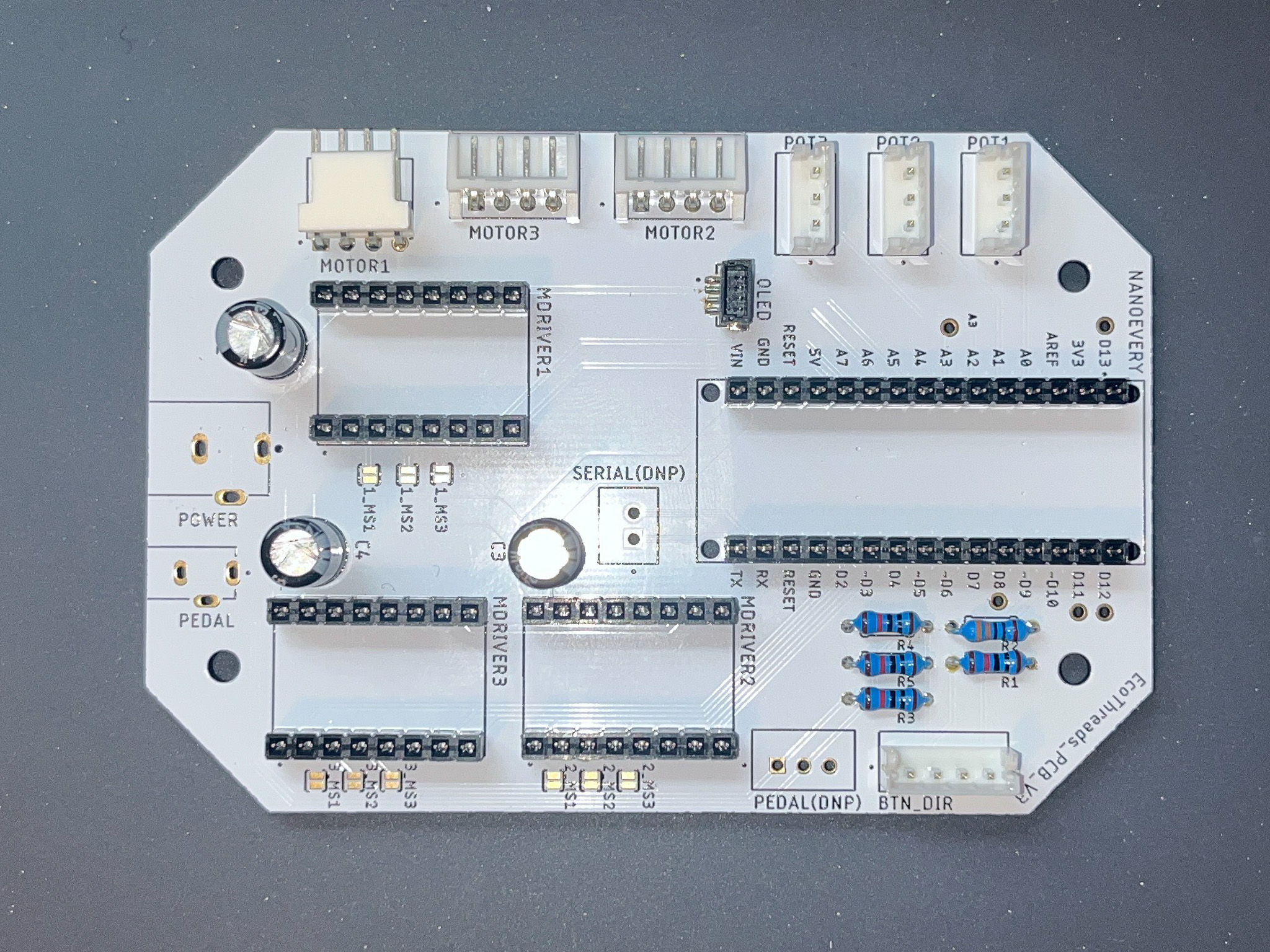
- Solder through-hole connectors for
PEDAL,POWERaccording to the Bill of Materials.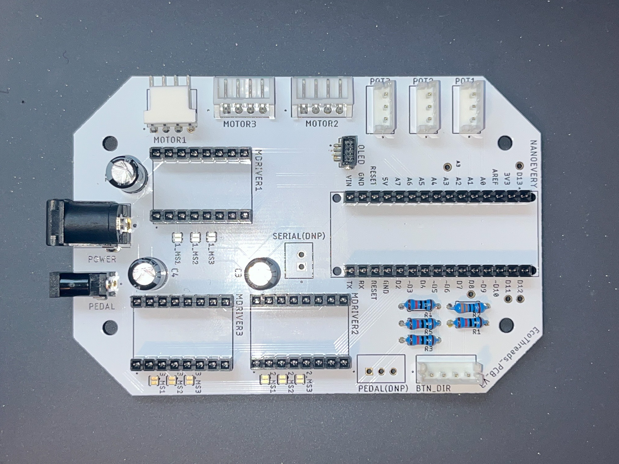
Soldering Wire Connectors
- Solder
pushbuttonconnectors according to the pin map below: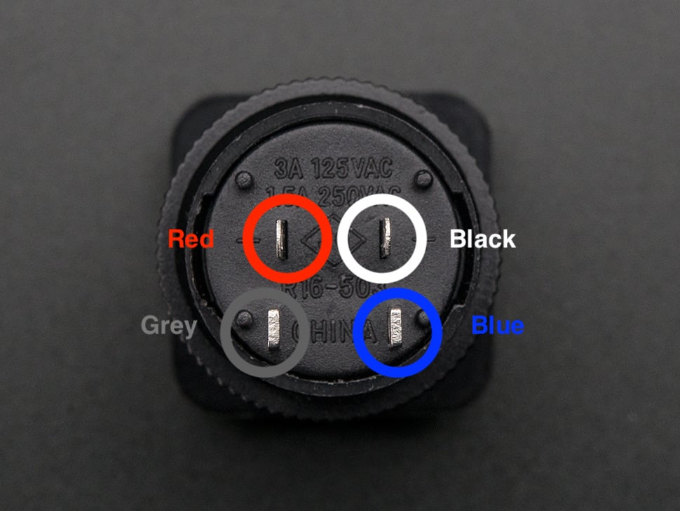
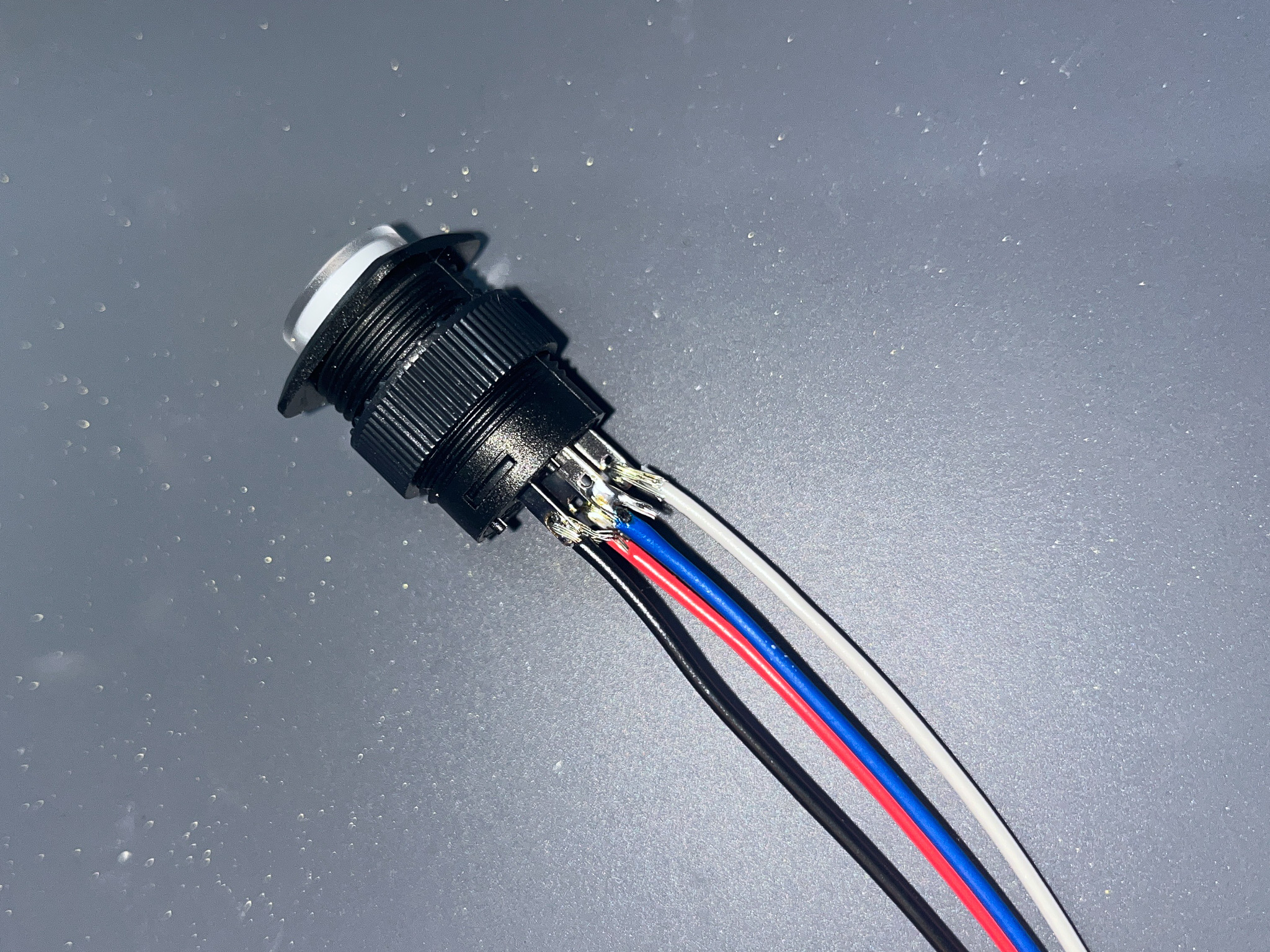
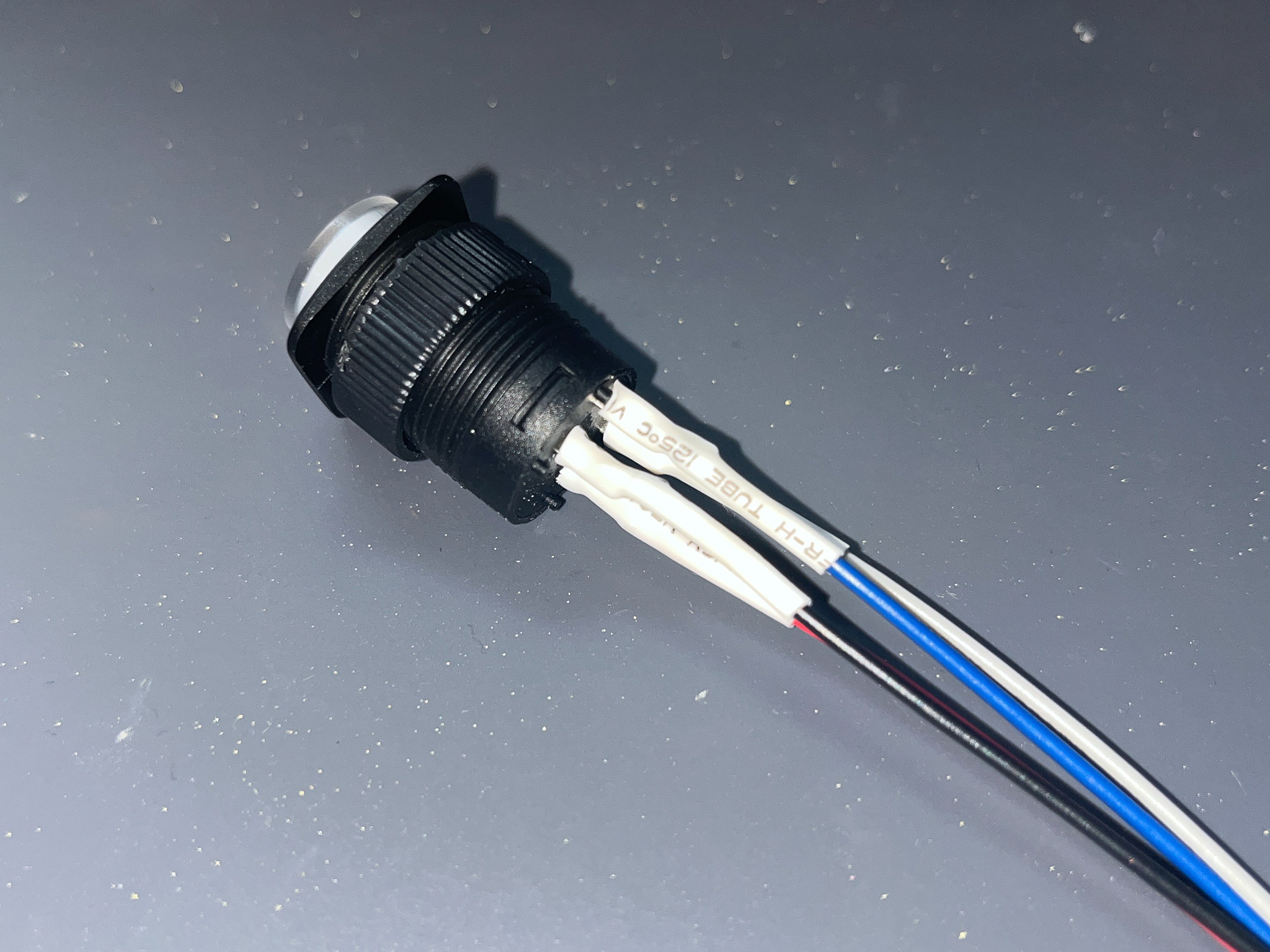
- Add shrink tube to each solder joints
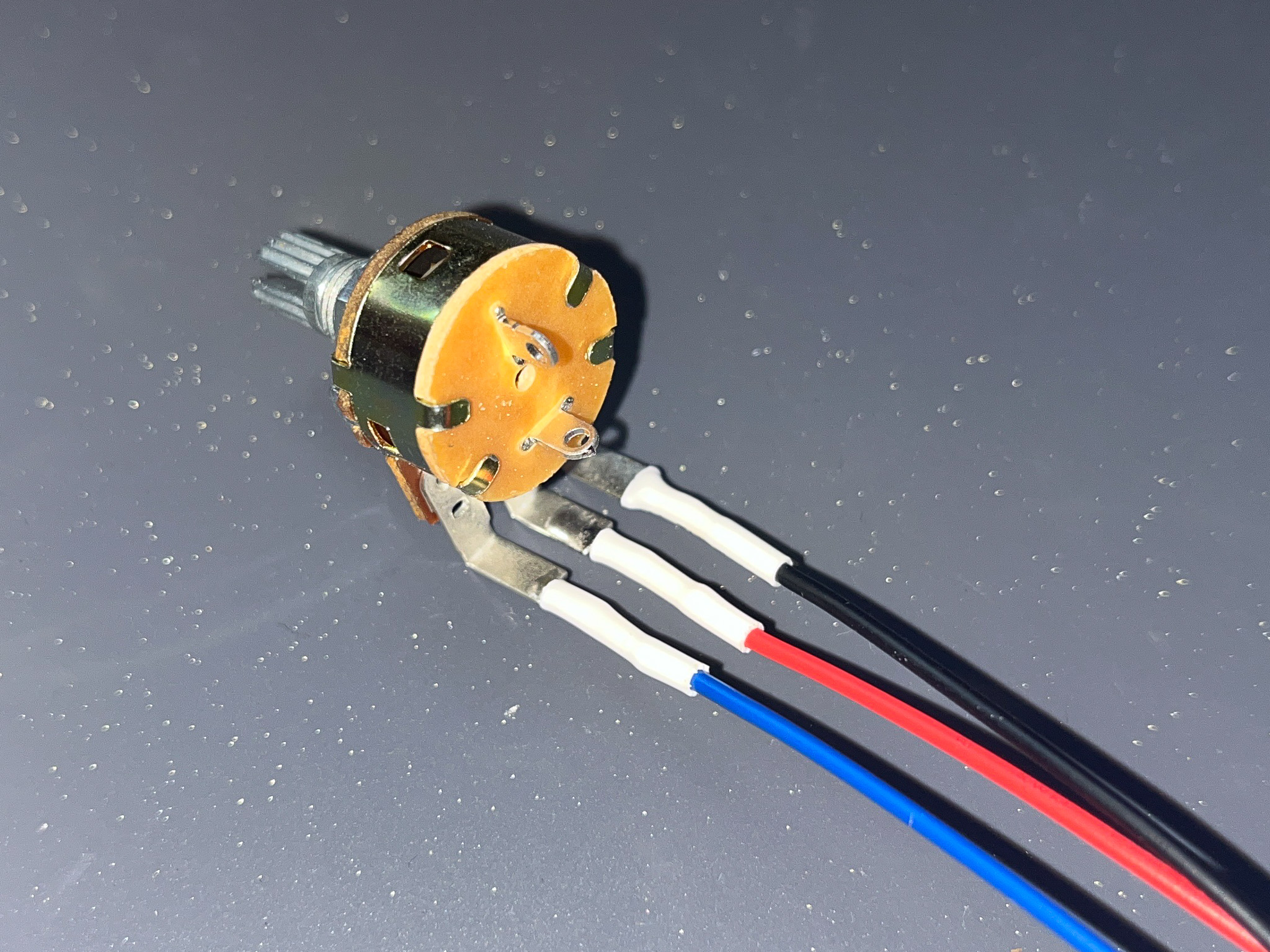
- Solder
potentiometerconnectors according to the pin map below: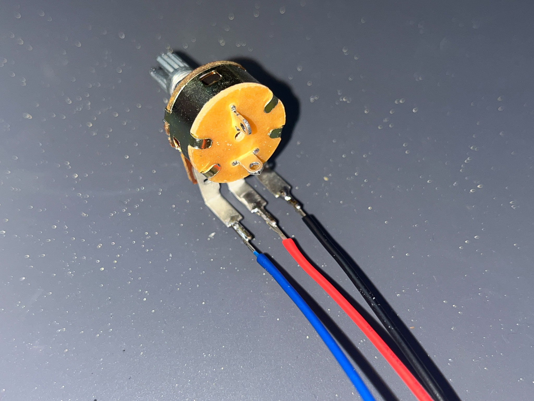
- Add shrink tube to each solder joints
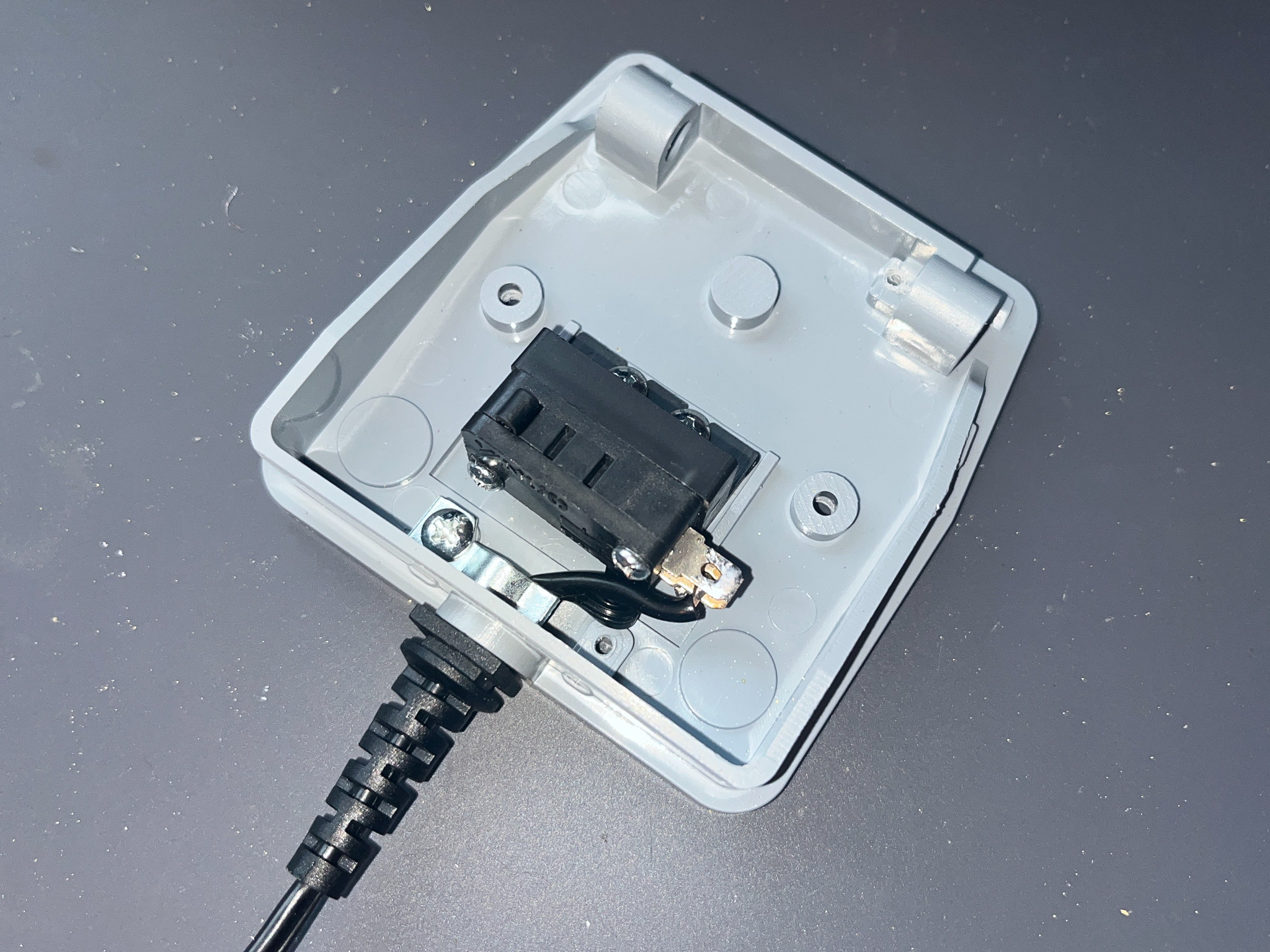
- Follow the instructions to open the
foot pedalcase, solderfoot pedalconnectors according to the pin map below: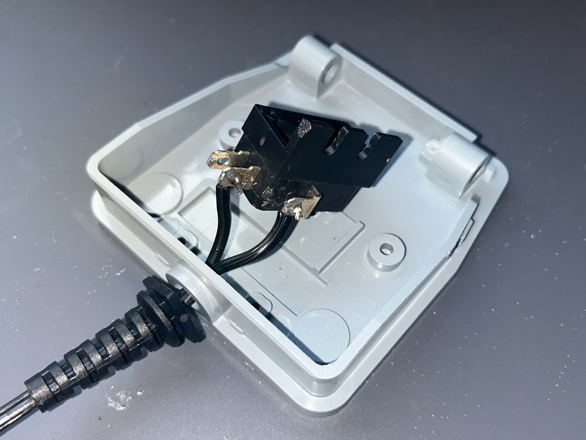
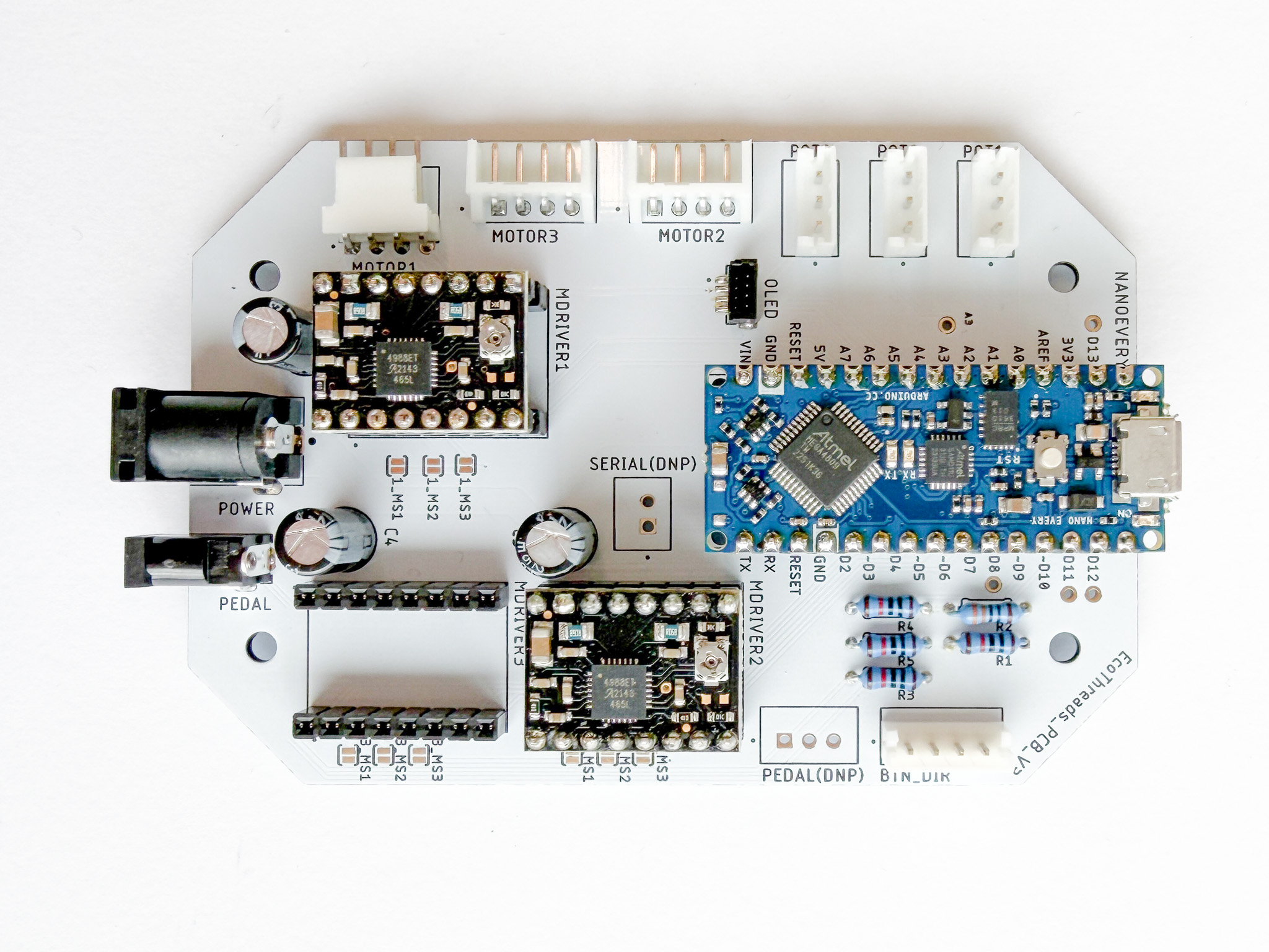
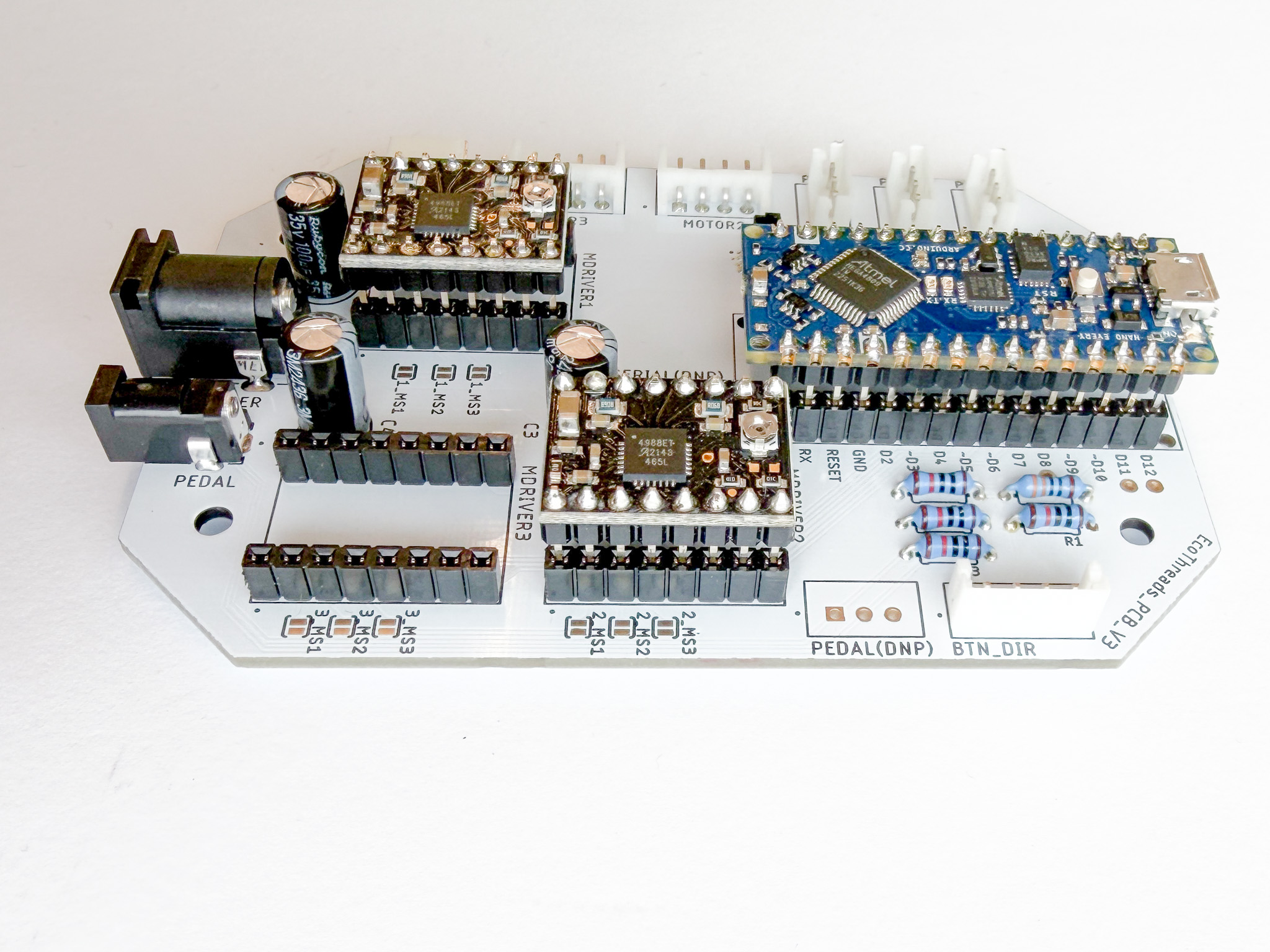
Assemble Breakout Boards onto the PCB
- Assemble all the breakout boards onto the PCB
Last updated on